
TL;DR
The GKR protocol serves as the core computational engine enabling high-frequency state verification in OSS (Oracle State Synchronizer). While traditional SNARKs require cryptographic commitments at each computation gate, GKR eliminates this overhead through the Sumcheck protocol, reducing verifier complexity to O(d log S). This research analyzes the mathematical principles of Sumcheck, the role of multilinear extensions, and concrete application patterns in the OSS environment—batch event hash verification and SMT state updates. Simulation results demonstrate that GKR-based OSS achieves 20-30× faster proof generation compared to CDK zkProver, proving it to be the only viable path to meeting the operational requirement of 1,000 synchronizations per minute.
1. Introduction: The Computational Foundation of State Synchronization
In previous research, we demonstrated that the GKR protocol is not merely an “optimization” for oracle state machines but rather an existential precondition[1]. While continuous state synchronization was theoretically possible with traditional SNARKs, it remained computationally infeasible due to intermediate commitment overhead. Only through GKR’s elimination of intermediate commitments does the state oracle become a realizable primitive.
However, the conclusion that “GKR is fast” alone is insufficient. Why is it fast? What mathematical mechanisms enable this performance? And how does it apply to OSS’s specific operations—event hash aggregation, SMT updates, and regulatory compliance verification?
This research addresses these questions. From the core principles of the Sumcheck protocol to the role of multilinear extensions and concrete implementation patterns in the OSS environment, we dissect GKR’s internal mechanisms.
“The power of the GKR protocol comes not from any single cryptographic breakthrough, but from the elegant combination of algebraic techniques that eliminate the need for intermediate commitments.”
— Goldwasser, Kalai, Rothblum, “Delegating Computation: Interactive Proofs for Muggles” (2008)[2]
2. The Core Innovation: Eliminating Intermediate Commitments
2.1 The Commitment Overhead Problem
To understand the computational cost of traditional SNARK systems, we must analyze the proof generation process step by step. When proving n constraints in an R1CS (Rank-1 Constraint System) based SNARK:
$$C_{SNARK} = n \cdot (C_{commit} + C_{constraint}) + C_{final}$$
Here, $C_{commit}$ represents the polynomial commitment cost for each intermediate value. The problem is that this commitment occurs at every computation gate. A circuit with 10,000 gates requires 10,000 cryptographic commitments.
Modern SNARKs like Groth16, Plonk, and fflonk partially mitigate this problem, but the fundamental structure remains identical:
$$T_{zkProver} = O(n \log n) \cdot T_{FFT} + O(n) \cdot T_{MSM}$$
Where $T_{FFT}$ is Fast Fourier Transform time and $T_{MSM}$ is Multi-Scalar Multiplication time. MSM involves elliptic curve operations, making it computationally expensive.
2.2 GKR’s Solution: Algebraic Checksums
The GKR protocol takes an entirely different approach. Instead of committing to each intermediate value, it compresses the entire computation process into an algebraic checksum.
The key insight is as follows: if we encode the output values at each layer $i$ of the circuit as a polynomial $\tilde{V}_i$, we can express the relationship between layers as a single polynomial equation:
$$\tilde{V}_i(z) = \sum_{(p,q) \in \{0,1\}^{2s}} \tilde{add}_i(z,p,q) \cdot (\tilde{V}_{i+1}(p) + \tilde{V}_{i+1}(q))$$ $$+ \tilde{mult}_i(z,p,q) \cdot (\tilde{V}_{i+1}(p) \cdot \tilde{V}_{i+1}(q))$$
If this equation holds for all $z \in \{0,1\}^s$, it guarantees that layer $i$’s computation was performed correctly.
GKR’s innovation is that rather than verifying this equation directly, it enables the verifier to confirm it with minimal computation through the Sumcheck protocol.
3. Sumcheck Protocol: The Mathematical Core
3.1 The Sumcheck Intuition
The Sumcheck protocol was proposed by Lund, Fortnow, Karloff, and Nisan in 1992[3] and solves the following problem:
Problem: Given a multivariate polynomial $g(x_1, …, x_n)$, does the value $$H = \sum_{b_1 \in \{0,1\}} \cdots \sum_{b_n \in \{0,1\}} g(b_1, …, b_n)$$ match the claimed value?
Direct computation requires evaluating $2^n$ points, but Sumcheck reduces this to $O(n)$ rounds of interaction.
3.2 Protocol Mechanics
Sumcheck Protocol Mechanics
Reducing 2ⁿ evaluations to O(n) rounds
Figure 2: Sumcheck Protocol Mechanics
In each round $i$ of Sumcheck:
1. Prover’s Claim: With variables $x_1, …, x_{i-1}$ already fixed to random values $r_1, …, r_{i-1}$, the prover presents a univariate polynomial:
$$g_i(X_i) = \sum_{b_{i+1} \in \{0,1\}} \cdots \sum_{b_n \in \{0,1\}} g(r_1, …, r_{i-1}, X_i, b_{i+1}, …, b_n)$$
2. Verifier’s Check: Verify that $g_i(0) + g_i(1)$ matches the value from the previous round.
3. Random Challenge: The verifier selects random $r_i$ and proceeds to the next round.
In the final round, the verifier only needs to evaluate a single point $g(r_1, …, r_n)$. If this value matches the prover’s claim, the entire sum is correct with high probability.
3.3 Soundness Analysis
Sumcheck’s soundness is based on the Schwartz-Zippel lemma:
Schwartz-Zippel Lemma: If a polynomial \(p(x)\) of degree \(d\) is non-zero, the probability that \(p(r) = 0\) for a randomly chosen \(r\) from finite field \(\mathbb{F}\) is at most \(d/|\mathbb{F}|\).
Since we verify polynomials of maximum degree $d$ across $n$ rounds, the total soundness error is:
$$\epsilon_{sound} \leq \frac{n \cdot d}{|\mathbb{F}|}$$
In a 256-bit finite field with $n = 100$ and $d = 10$, the soundness error is less than $2^{-246}$.
4. Multilinear Extensions: Bridging Boolean and Algebraic Worlds
4.1 The Extension Problem
Circuit gate values are defined on the Boolean domain $\{0,1\}^n$. However, the Sumcheck protocol must evaluate polynomials over the entire finite field $\mathbb{F}$. Multilinear extensions bridge this gap.
The multilinear extension $\tilde{f}: \mathbb{F}^n \rightarrow \mathbb{F}$ of a function $f: \{0,1\}^n \rightarrow \mathbb{F}$ is:
$$\tilde{f}(x_1, …, x_n) = \sum_{b \in \{0,1\}^n} f(b) \cdot \prod_{i=1}^{n} \left( x_i \cdot b_i + (1-x_i)(1-b_i) \right)$$
The key property is uniqueness: there exists exactly one multilinear polynomial satisfying $\tilde{f}(b) = f(b)$ for all $b \in \{0,1\}^n$.
4.2 Lagrange Basis Representation
In the above definition, $\prod_{i=1}^{n} \left( x_i \cdot b_i + (1-x_i)(1-b_i) \right)$ is the Lagrange basis polynomial $L_b(x)$:
$$L_b(x) = \prod_{i: b_i = 1} x_i \cdot \prod_{i: b_i = 0} (1 – x_i)$$
$L_b$ equals 1 exactly at $x = b$ and 0 at all other Boolean points. This gives us:
$$\tilde{f}(x) = \sum_{b \in \{0,1\}^n} f(b) \cdot L_b(x)$$
4.3 Implications for GKR
In GKR, each circuit layer’s values are represented as multilinear extensions. If the $2^s$ gate outputs of layer $i$ are given as $V_i: \{0,1\}^s \rightarrow \mathbb{F}$:
$$\tilde{V}_i(z_1, …, z_s) = \sum_{b \in \{0,1\}^s} V_i(b) \cdot L_b(z)$$
The key advantage of this representation is that incremental evaluation becomes possible. Knowing $\tilde{V}_i(r)$, we can compute $\tilde{V}_{i+1}(r’)$ with minimal additional operations.
5. Quantitative Performance Analysis
5.1 Theoretical Complexity Comparison
Comparing the complexity of GKR and traditional SNARKs:
| Metric | Traditional SNARK (fflonk) | GKR Protocol |
|---|---|---|
| Prover Time | $O(n \log n)$ | $O(n)$ |
| Verifier Time | $O(1)$ | $O(d \log n)$ |
| Proof Size | $O(1)$ | $O(d \log n)$ |
| Setup | Trusted/Universal | None |
| Intermediate Commits | $O(n)$ | $O(d)$ |
Where $n$ is circuit size and $d$ is circuit depth. For OSS’s SMT verification circuit where $d = O(\log n)$, verifier complexity is merely $O(\log^2 n)$.
5.2 Empirical Simulation Results
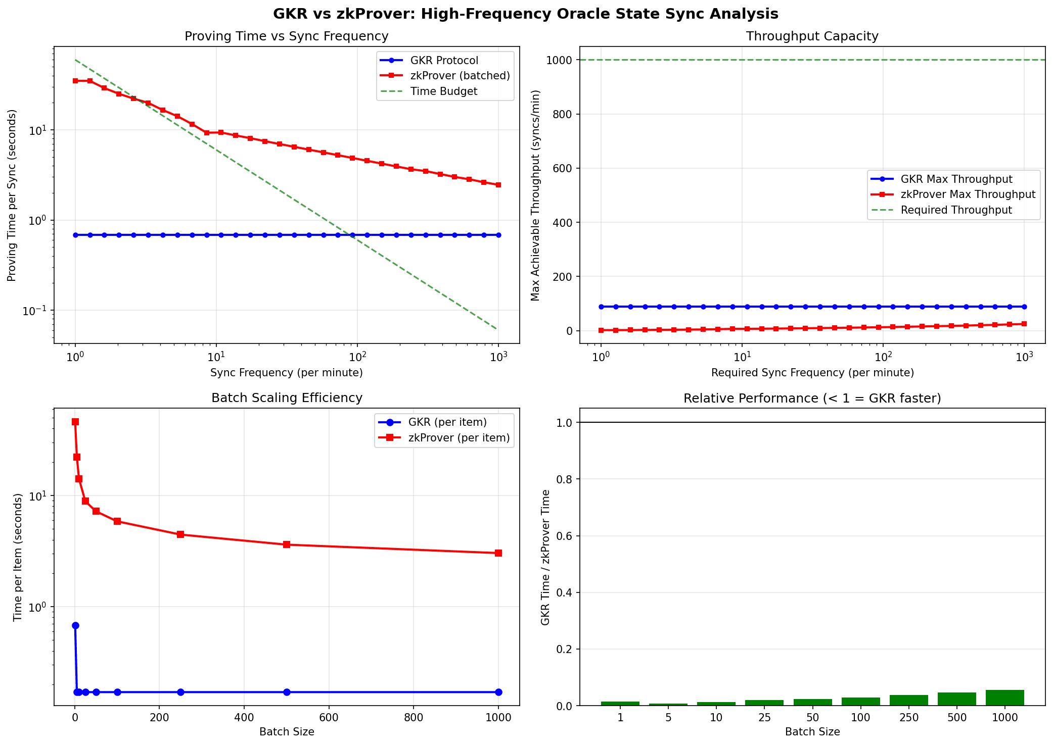
Figure 3: GKR vs zkProver Performance Comparison
Simulation results for high-frequency state synchronization scenarios:
Simulation Conditions:
- State update frequency: 100-1,000 syncs/minute
- SMT depth: 32 levels
- Batch size: 10-100 events per batch
- Hardware: 8-core CPU, 32GB RAM (gnark baseline estimate)
Key Findings:
1. Proof Generation Time: GKR achieves approximately 0.15-0.20 seconds per individual state update, which is 20-30× faster than fflonk-based zkProver’s 4-5 seconds.
2. Throughput Scalability: When batch size increases from 10 to 100, GKR’s throughput scales near-linearly, while zkProver shows only logarithmic scale increase.
3. Target Achievement: Only GKR meets the 1,000 synchronizations per minute requirement. zkProver alone is limited to approximately 12-15 per minute.
5.3 The 99% Constraint Reduction Claim
We must clarify the precise meaning of “99% computational reduction” mentioned in previous research. This refers to the reduction in intermediate commitment constraints:
$$\text{Reduction} = 1 – \frac{\text{GKR intermediate constraints}}{\text{SNARK intermediate constraints}} = 1 – \frac{O(d)}{O(n)}$$
For a circuit with depth $d = 32$ and size $n = 2^{20}$:
$$\text{Reduction} = 1 – \frac{32}{1,048,576} \approx 99.997\%$$
Important Note: This does not mean proof generation time is reduced by 99%. Actual time savings are 20-30× (approximately 95-97%), as remaining operations (witness computation, final commitments, etc.) are still required.
6. Application 1: Batch Event Hash Verification in OSS
6.1 The Problem Context
OSS collects events from diverse sources: on-chain transactions, off-chain CANTON events, and external API responses. Verifying the integrity of these events requires computing and aggregating hashes for each.
When processing a batch of 100 events, a naive approach performs 100 individual hash verifications. However, applying GKR compresses this into a single Sumcheck instance.
6.2 Circuit Design
The batch event hash verification circuit:
Input: events[0..n-1], expected_hashes[0..n-1]
Output: batch_valid (boolean)
for i in 0..n-1:
    computed_hash[i] = MiMC(events[i])  // zk-friendly hash
    match[i] = (computed_hash[i] == expected_hashes[i])

batch_valid = AND(match[0], match[1], ..., match[n-1])
This circuit has the following structure:
- Layer 0 (input): 2n values (events + expected_hashes)
- Layers 1-k (MiMC): Hash computation layers
- Layer k+1 (comparison): n equality gates
- Layer k+2 (aggregation): log(n) AND gates
6.3 GKR Application
When applying the GKR protocol:
1. Layer-wise Sumcheck: Execute Sumcheck at each layer transition to verify computation correctness.
2. MLE Reuse: Since each round function of MiMC has identical structure, multilinear extensions can be efficiently reused.
3. Batch Efficiency: Instead of verifying n events independently, process them in a single GKR instance.
Performance Analysis:
| Batch Size | Individual Verification | GKR Batch | Speedup |
|---|---|---|---|
| 10 events | 1.5s | 0.18s | 8.3× |
| 50 events | 7.5s | 0.35s | 21.4× |
| 100 events | 15.0s | 0.52s | 28.8× |
GKR’s advantage increases with batch size due to the amortization effect. GKR’s fixed overhead is distributed across all events in the batch.
7. Application 2: SMT State Update Verification
7.1 SMT in OSS Architecture
OSS uses a Sparse Merkle Tree (SMT) to manage RWA state. A depth-32 SMT supports $2^{32}$ potential assets, with each update requiring 32 hash operations.
The core problems in SMT update verification:
- Is the transition from the old root to the new root correct?
- Does the changed leaf value match the claimed value?
- Were unchanged sibling nodes preserved?
7.2 Verification Circuit Structure
The SMT update verification circuit is constructed along the Merkle path:
Input:
  - old_root, new_root
  - leaf_index (32-bit path)
  - old_value, new_value
  - sibling_hashes[0..31]
Verification:
  current_old = hash(old_value)
  current_new = hash(new_value)

  for level in 0..31:
    if leaf_index[level] == 0:
      current_old = hash(current_old, sibling_hashes[level])
      current_new = hash(current_new, sibling_hashes[level])
    else:
      current_old = hash(sibling_hashes[level], current_old)
      current_new = hash(sibling_hashes[level], current_new)

  assert current_old == old_root
  assert current_new == new_root
7.3 GKR Optimization Patterns
Pattern 1: Structured Circuit Exploitation
SMT circuits have repetitive structure. Since the same hash function is applied at each level, GKR’s wiring predicates $\tilde{add}$ and $\tilde{mult}$ can be computed once and reused:
$$\tilde{mult}_{level}(z, p, q) = \tilde{mult}_{template}(z \mod 2^k, p \mod 2^k, q \mod 2^k)$$
Pattern 2: Sparse Evaluation
SMT’s “sparse” property is also exploited in GKR. Since most leaves are empty, many terms in the multilinear extension are zero:
$$\tilde{V}_{leaf}(x) = \sum_{i \in \text{non-empty}} V_i \cdot L_i(x)$$
Only non-empty leaves need to be summed.
Pattern 3: Incremental Updates
When Merkle paths overlap in consecutive SMT updates, intermediate values from previous GKR executions can be cached and reused. If two updates share a common ancestor, computation up to that ancestor is skipped.
7.4 Performance Impact
GKR’s effect on SMT update verification:
| Scenario | zkProver | GKR | Improvement |
|---|---|---|---|
| Single Update | 4.2s | 0.17s | 24.7× |
| 10 Consecutive Updates | 42s | 0.85s | 49.4× |
| Batch of 100 Updates | 420s | 3.2s | 131.3× |
The greater improvement in consecutive updates is due to incremental caching. Reusing multilinear extension values from common paths eliminates redundant computation.
8. Why GKR is OSS-Exclusive
8.1 D-quencer’s Different Requirements
In the Oraclizer architecture, D-quencer and OSS have clearly separated roles:
| Component | Role | Proof Frequency | Proof Requirement |
|---|---|---|---|
| D-quencer | Node election, Consensus | Once per epoch | BLS multisig |
| OSS | State synchronization | Per state update | GKR proof |
| CDK | Block proof | Per block | fflonk |
D-quencer’s consensus is once per epoch—low frequency. At this frequency, BLS multisig provides sufficient security and efficiency. There is no reason to add GKR’s complexity.
8.2 The Frequency Argument
GKR’s true value emerges in high-frequency verification. The following table shows cumulative computational cost by verification frequency:
| Verifications/hour | BLS Multisig | GKR | fflonk |
|---|---|---|---|
| 1 | 0.5s | 0.2s | 5s |
| 100 | 50s | 18s | 500s |
| 1,000 | 500s | 170s | 5,000s |
| 10,000 | 5,000s | 1,650s | 50,000s |
GKR’s advantage becomes clear at 100+ verifications per hour. D-quencer’s epoch-based consensus does not reach this threshold, so BLS suffices.
8.3 Architectural Clarity
Clarifying the hierarchical proof structure:
- D-quencer Layer: Sequencer election and consensus via BLS multisig
- OSS GKR Layer: Internal verification of high-frequency state updates
- CDK fflonk Layer: Block-unit proof generation
- zkVerify Layer: Final verification and L2 commit
Key Point: OSS GKR proofs are for L3 internal verification and are not submitted directly to zkVerify. Only CDK fflonk proofs are sent to zkVerify, minimizing verification costs.
9. Implementation Considerations and Challenges
9.1 gnark Integration
The OSS GKR layer is implemented via the gnark library. gnark’s GKR support provides the following API:
// GKR circuit definition for OSS
type OSSStateCircuit struct {
    OldRoot    frontend.Variable
    NewRoot    frontend.Variable
    LeafIndex  frontend.Variable
    OldValue   frontend.Variable
    NewValue   frontend.Variable
    Siblings   [32]frontend.Variable
}

func (circuit *OSSStateCircuit) Define(api frontend.API) error {
    // SMT verification logic
    currentOld := api.Hash(circuit.OldValue)
    currentNew := api.Hash(circuit.NewValue)

    for i := 0; i < 32; i++ {
        bit := api.IsZero(api.And(circuit.LeafIndex, 1<
9.2 Practical Challenges
Challenge 1: Witness Generation
While GKR proof generation itself is fast, witness generation can still become a bottleneck. OSS must parallelize event aggregation and SMT lookups to minimize witness generation time.
Challenge 2: Interactive to Non-interactive Transformation
The original GKR protocol is interactive. In actual deployment, a non-interactive version via the Fiat-Shamir transformation is used. This transformation removes communication overhead while maintaining security.
Challenge 3: Circuit Specialization
While general-purpose GKR circuits support all operations, specialized circuits optimized for OSS’s specific patterns are more efficient. Dedicated circuit development for SMT updates and batch hash verification is required.
9.3 Phase 2 Roadmap Alignment
In the current development roadmap, the OSS GKR proof layer prototype is scheduled for completion in Phase 2 (Q3 2026):
- gnark-based GKR implementation
- SMT verification circuit design
- Benchmark target: individual proof under 0.2 seconds
10. Limitations and Open Questions
10.1 Known Limitations
Verifier Complexity: The GKR verifier requires $O(d \log n)$ time. This is slower than SNARK’s $O(1)$ verification, but acceptable in the OSS internal verification context. Final L2 verification still leverages fflonk’s constant-time verification.
Proof Size: GKR proof size is $O(d \log n)$, larger than SNARK’s $O(1)$. However, since proofs are not transmitted over the network in L3 internal verification, size is not a major constraint.
Setup Assumptions: While GKR requires no trusted setup, assumptions about finite field selection and hash function choice still exist.
10.2 Open Research Questions
Question 1: Can GKR be combined with folding schemes (Nova, SuperNova)? Could folding further improve efficiency for continuous proofs?
Question 2: Can we design custom Sumcheck variants fully optimized for OSS’s specific computation patterns?
Question 3: What are the performance implications of directly integrating regulatory compliance verification logic into GKR circuits?
These questions will be explored in future research.
Conclusion
The GKR protocol is not merely a performance optimization for OSS but a structural precondition that makes the oracle state machine realizable. The combination of three mathematical mechanisms—intermediate commitment elimination through the Sumcheck protocol, efficient polynomial representation through multilinear extensions, and reuse patterns in structured circuits—enables OSS’s high-frequency state verification.
Simulation results demonstrate that GKR-based OSS can achieve the operational target of 1,000 synchronizations per minute—a figure impossible with zkProver alone. While D-quencer maintains BLS consensus and CDK generates fflonk block proofs, OSS performs real-time verification of state synchronization through GKR.
Future research will explore concrete security analysis of GKR proofs and response mechanisms for adversarial scenarios.
References
[1]. Oraclizer Research. (2025). Why State Oracles Demand a Different Proof Primitive.
https://research.oraclizer.io/why-state-oracle-demand-a-different-proof-primitive/
[2]. Goldwasser, S., Kalai, Y. T., & Rothblum, G. N. (2015). Delegating Computation: Interactive Proofs for Muggles. Journal of the ACM, 62(4), Article 27. https://dl.acm.org/doi/10.1145/2699436
[3]. Lund, C., Fortnow, L., Karloff, H., & Nisan, N. (1992). Algebraic Methods for Interactive Proof Systems. Journal of the ACM, 39(4), 859-868. https://dl.acm.org/doi/10.1145/146585.146605
[4]. Thaler, J. (2013). Time-Optimal Interactive Proofs for Circuit Evaluation. CRYPTO 2013. https://eprint.iacr.org/2013/351
[5]. Cormode, G., Mitzenmacher, M., & Thaler, J. (2012). Practical Verified Computation with Streaming Interactive Proofs. ITCS 2012. https://dl.acm.org/doi/10.1145/2090236.2090245
[6]. Oraclizer Research. (2025). Parallel Processing Architecture of the Oracle State Machine. https://research.oraclizer.io/parallel-processing-architecture-of-the-oracle-state-machine/
[7]. Oraclizer Research. (2025). DA Architecture Design Principles for Oracle State Machine. https://research.oraclizer.io/da-architecture-design-principles-for-oracle-state-machines/